
Why Put Flow Simulation on an Injection Machine?

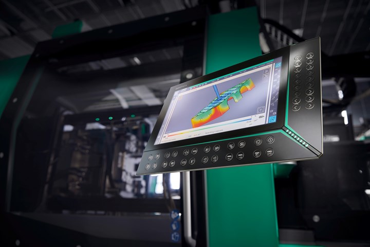
At Fakuma 2021, Engel’s sim link enables simulation software and injection machine controls to talk to each other in the same language. (Photo: Engel)
I’ve been noodling that question around in my head for the last three years, since injection machine suppliers like Arburg, Engel, Wittmann Battenfeld and Sumitomo (SHI) Demag started showing up at trade shows with mold-filling displays on their machine controller screens. I’ve been writing about plastic flow simulation since 1984, and I consider it to be one of the most important technological advances in molding I’ve seen in my career.
So, naturally, I was excited to see it applied directly at the molding press. But the question was, what can you do with it there?
Machine-integrated simulation seems to be still in the developmental stages, and information about its practical utility has trickled out gradually. At Fakuma 2018, the first public appearance of such machine-integrated simulation, Arburg stated that this involves giving the molding press information about the part geometry, which it has never had before. Intriguing, I thought, but not highly illuminating.
Next, at K 2019, Engel offered one hint of how this approach could help engineers perform more accurate simulations: Using Engel’s e-connect customer portal, the engineer could go online and select the machine intended for a molding job, and then download from Engel the parameters for machine capabilities—speeds, pressures, acceleration ramps, and temperatures. That way, Engel said, the simulation wouldn’t recommend process values that the machine could not achieve. Sounds sensible, but doesn’t require a display of mold filling on the machine’s control panel.
Arburg’s integration of flow simulation on its Gestica controller (aXw Control FillAssist) enables real-time animation of mold filling correlated with screw position. (Photo: Arburg)
Also at K 2019, Arburg unveiled a new digital “filling assistant,” which provides a 3D graphic of the degree of part filling relative to screw position, which can be animated in real time. Huh, I thought. Wonder what you can do with that.
It started coming together clearer for me with Engel’s news from Fakuma 2021 that its sim link machine interface is now available for Cadmould simulation software from Simcon, in addition to Autodesk’s Moldflow. As noted in a recent news item, Simcon illuminated the importance of such integration: For one thing, Simcon pointed out that injection molding simulations can capture process parameters in a format different from that of the actual press control settings, forcing process technicians to translate the information into a format the machine can utilize. Second, if the real-world process is tweaked from what the simulation called for, those changes often never get back to the engineers that ran the simulation, limiting their ability to learn what needed to be adjusted. The benefit of sim link is that it not only translates the simulation software into parameters the machine can understand, but it records and saves any changes to the process from what the simulation specified, so the engineers can see how what Cadmould called for differs from real-world molding of the part.
Now this was starting to make sense to me, and it led me back to Arburg’s announcement of its “aXw Control FillAssist” real-time animation of mold filling on the press, correlated with screw position. I’m just spitballing here, but consider this potential scenario:
The molder notices some defects in the molded parts—flash, shorts, burns, weld lines, flow lines, etc.—that may be related to the part or tool design but could possibly be ameliorated with process adjustments.
One response could be to send the affected parts back to the simulation engineer—who may not be on-site at the molding plant—and wait for a proposed solution based on rerunning the simulation with modified process conditions.
Or … perhaps a process technician at the molding plant could examine the flow simulation on the press control panel and observe exactly when and where the problems occurred during the filling process. Perhaps that examination might suggest some tailoring of the process—maybe an adjustment of the injection speed or pressure profile, correlated with the melt’s arrival at the problem areas in the part. Besides saving time (and perhaps money), this solution might benefit from the molding technician’s closer familiarity with the machine and actual molding than might be the case with the simulation engineer (no offense intended).
What I’d really like to see is first-hand experience from a molder with this new integration technology. Where the rubber meets the road, so to speak. That’s where we’ll learn how, and how much, this innovation could help advance the state of the art in injection molding.
Leave a Reply